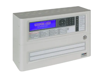
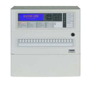
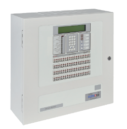
The Morley-IAS DX Connexion panel is ideally suited for use in the protection of small to medium sized buildings. All in all, a compact, high performance, feature rich, economical fire alarm control panel designed to help both the installer and the end user. The DX Connexion is an enhancement of the Morley-IAS Dimension panel range, connecting the traditional Morley-IAS qualities of reliability, flexibility and value with advanced features and intuitive functionality.
Preloader Close
s
p
e
e
d
t
e
c
n
o
l
o
g
y
-
Mail Us On
speedtech_rjt@hotmail.com
-
Make a Call
98242 99869
-
Mail Us On
speedtech_rjt@hotmail.com
-
Make a Call
98242 99869

DXc2 TWO-LOOP CONTROL PANEL
- Category:MORLEY EN
- Brand:HONEYWELL MORLEY
- Model No:DXc2
NETWORKING FEATURES
• Network up to 16 loops (16x1 loop
panels, 8x2 loop panels, 4x4 loop panels
or any mix up to max 16 loops)
• True peer-to-peer and fault tolerant
network for high system reliability
• BS5839 part 1 compliant network
PANEL FEATURES
• Disable all relays
• Optional 40, 80 or 160 zone alarm LEDs
• Easy 5 key-press set-up
• Large blue LCD display
• Supports USB upload/download
• Alpha-numeric style keypad
and navigation keys
• Option to upload a company logo
• 160 zone compact mimic support
• Panel buzzer ‘mute’ in engineering mode
• Up to 72 hour standby
• 3 min Inhibit Timer function
• Printer support
• Remote LED Support
• Level -3 configurable Passcode support
• Sounder Synchronization
• Fire Transmission & Keysafe Support
• Fire Transmission LED Support
SOFTWARE FEATURES
• PC configuration software
(supplied with panel)
• 80 fire zones (can be used
with or without LEDs)
• 7 day timers
• Event logging
• Onboard diagnostics
• Class change function
• Coincidence and verification detection
for false alarm management
• Sensitivity adjustment e.g. between day and night
• Input/output logic
• Enhanced zone support up to 160 LEDs
• Alternative zone referencing scheme
• Programming optional language support
• Event Logic support
• Remote LED Event Logic
HARDWARE FEATURES
• Battery backed real-time clock (2 & 4 loop)
• 2 independent sounder circuits
• 500mA loop driver
• 2 x onboard monitored inputs
• Optional programmable keyswitch
for selected functions
• Plug-in connectors
Output Relays:
Fire relay: Single pole changeover 24V DC 1A
Extended: Single pole changeover 24V DC 1A
Aux relay: Programmable single pole
changeover 24V DC 1A
Onboard Data Ports:
1 x RS485 (Repeater connection) 1 x
PC Programming Port4 Optional
Ports:
RS232 third party protocol interface
Sounder Circuits:
2 output circuits, 1A per circuit.1
| Documentation | Download |
|---|---|
| resources_1606770679DXc1_DXc2_DXc4.pdf | Download |
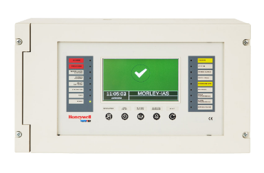
USER INTERFACE Display:6x40 character (240x64 pixels) blue liquid crystal display with backlight illumination Control Keys: Evacuate, Silence/Resound, Mute Buzzer, Extend Delay, System Reset, Show Alarm Zones Programming Keys: 12 button alpha numeric key pad inc cancel and return keys plus 4 navigation keys and an OK key Programming Keys: 2 independent programmable function keys and LED indicators Indicators: Fire, Fault, Disablement, Test, Buzzer Muted, Delayed Mode, Sounders Silenced, Sounders Disabled and Power. Also dedicated fault LEDs for System Fault, Sounder Fault, Supply Fault and Earth Fault. 40, 80 or 160 LED fire zone indicators optional.